Author Archives: csprick

Manikin voices

We use the Laerdal manikins and are generally very pleased with them.  However, the voice can be problematic.  Here are some of the issues:

  • Sound goes crackly sometimes – it seems that the IP stream gets corrupted somehow.  Restarting the Voice app fixes it, but this shouldn’t happen.
  • There are so many volume controls! Novice users get confused about all the places to control volume/mute and it’s often difficult for the next person to work out what the previous person did.
  • The Mic’s we had were pretty low quality.

My wife recently started a podcast, so I got to play with mics and other prosumer audio kit over the holidays.

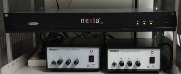
Doni from Flindes AV/IDS found an old Digital Signal Processor sitting around unused and said I could use it for this project.  It is a Biamp Nexia CS and has 10 mic/line inputs and 6 line outputs.  Since this is a DSP, it is all computer configurable and you can mix/match all the inputs and outputs to get exactly what you want.

nexia and amps

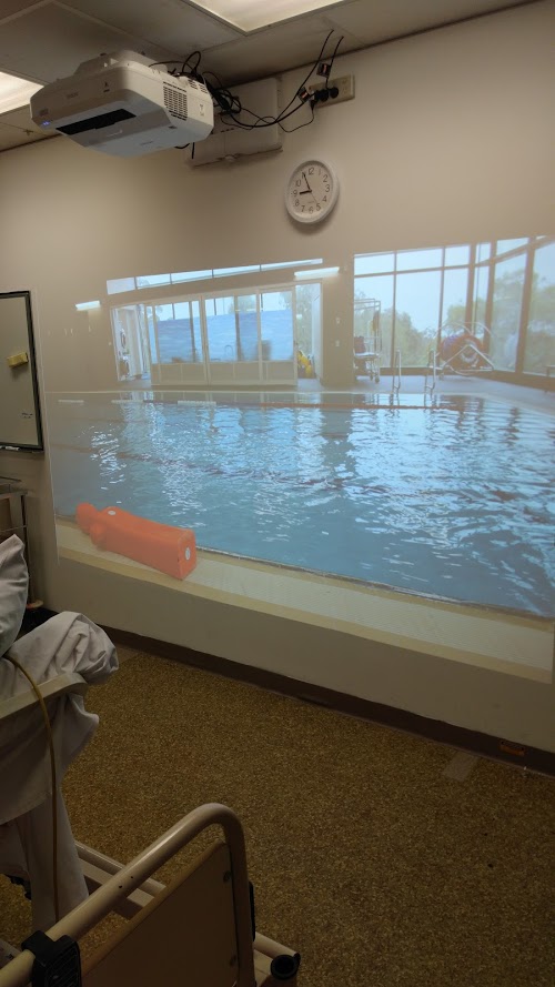
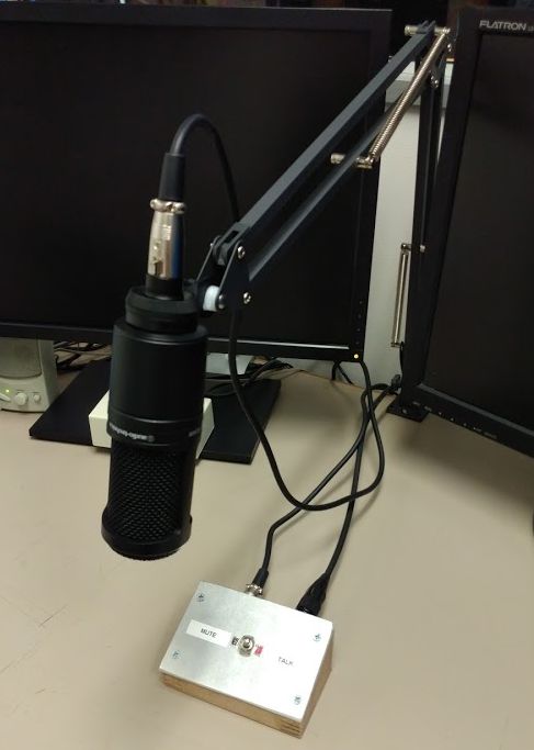
The idea was to get some nice’ish condenser mics (Audio Technica AT2020 $108), mount them on boom arms (Ikea Tertial desk lamps $15) and put a speaker under the bed to bypass the manikin voice channel completely.  Since the DSP has so many channels and Sim1 and Sim2 are adjacent to each other, this device should be able to serve both rooms.  Ideally this would serve both the Manikin voice channels, but also the room audio.

mic desk setupmute switch and mic

For each room, we would have:

  • Mic in the control room (input) to a speaker under the bed (output) – with a mute switch
  • Mic in the sim room (input) that feeds both a speaker in the control room (output) as well as the MLS audio encoder (different output)

So, that’s 2 inputs and 3 outputs per room = 6 outputs total, so this should work!  I haven’t tackled the room mic channel yet – not sure if we could/should have echo cancellation on this channel.  That will be another post.

For Sim3, we’ll run a Pre-Me ($111) as a preamp for the mic instead of the Nexia.  When we get our new facility, we’ll get a big Tesira to run all of the sim rooms together.

pre-me and amp

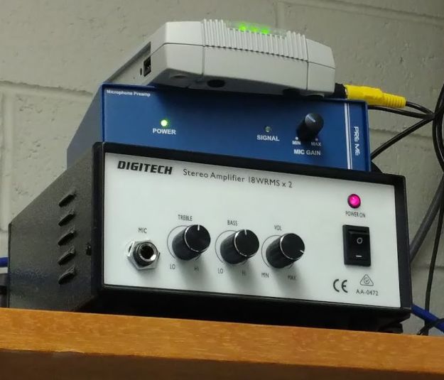
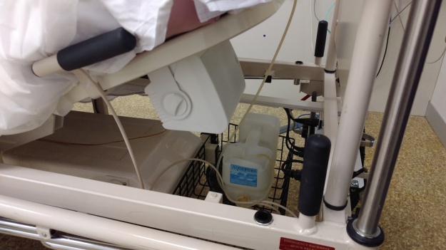
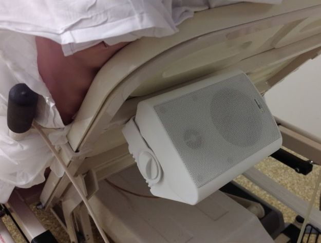
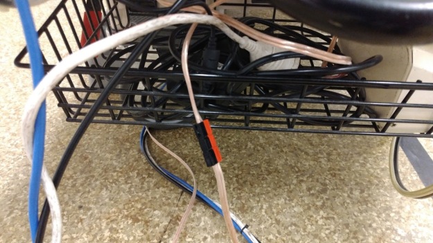
In all cases, the speakers are driven by a simple auido amp – AA0472 $40 from Jaycar.  The speakers (4″ indoor/outdoor $70 for the pair) are mounted under the backrest of the bed with some tek screws into the frame.  The beds can be disconnected and moved around using a set of anderson connectors on the speaker cable near the foot of the bed with all of the other connections (power, data, air) to the manikin.

speaker clearancespeaker mounting

anderson connector speaker disconnect

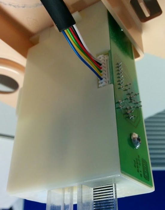
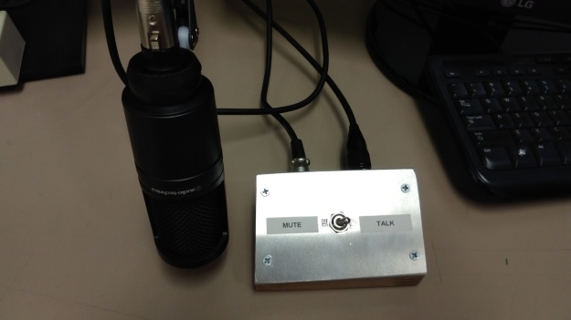
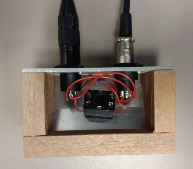
These mics all use balanced XLR connections and because they are condenser mics, phantom power.  The general consensus on the mic muting is that shorting the two signal pins will provide good pop free muting and will not affect the phantom power which is applied between the signal wires and ground.  So I whipped up a switch box for each room that is essentially a passthrough with a switch to short pins 2 and 3 (pin 1 is ground).

mute switch wiring

This new system is working great!  Everyone loves it.

Was it worth it?

Well, we’ve had this in place for a while now and have been using it mostly for BLS sessions in different environments.  I think it has been very successful for this.

ambulancepool

I would like to use it more for other sim sessions, but there are a couple hurdles yet to go.

  • Content – I’ve taken some photos around the place, including a massive panorama of the resus room down at Flinders Medical Centre ED.  These are great.  I’ve also recorded some ambient sounds to add some audio elements to the mix.  I think the issue becomes the viewpoint.  These rooms are set up so that the projector wall is off to the side, or optionally the foot of the patient bed.  This works great for non-bed type environments, but doesn’t work seamlessly when you do have a patient on a bed.
  • Video – The still photos with ambient sounds are great, but it might be even better to have some video content.  Of course this ramps up all of the requirements – shooting, streaming, realtime player for a RPi.

Not insurmountable, just hurdles that we haven’t jumped yet – mostly due to lack of time and higher priorities.  Stay tuned for further updates…

Software for projectors

There are many ways to do this.  Here’s what I chose to do.  First some specs:

  1. display still image full screen
  2. play sound file on a loop
  3. allow selection of images and sounds (mix and match)
  4. easy to use interface
  5. central storage for common updates
  6. play video (with sound) full screen

HTML5 includes tags for images, audio and video that can be played full screen and looped very easily.  A convenient place to keep them is on our departmental server, so web pages and media stored there seems like an obvious choice.

One option would be to create a selection page to choose a variety of ‘scenes’ with thumbnails or links to other pages that display the images/sounds/videos.  Still an easy option, but it’s not where I started (too easy?).  May revisit this in future.  Could add some links to the bottom of the form (see next).

I chose to go with a pair of php pages.  The first one is a form with a couple drop-down (select) elements to chose the image and sound from lists pulled from the directories (images, sounds, videos).  Form submission calls a second php page that builds the actual display html.

Now to try playing video.  Unfortunately, although both Chromium and Midori will both play videos, it seems that the CPU on the Pi (zero) is not able to play video smoothly unless it is very small (resolution/size).  The solution is to use the OMXplayer which is optomised to play video using the GPU.  This works great at full screen size.  OMX player is pretty basic and works from the command line.  It allows some switches at runtime (looping, resolution, etc) and some keyboard commands to modify playback (skip, pause, etc).  Full reference at: https://www.raspberrypi.org/documentation/raspbian/applications/omxplayer.md Now I just have to work out how to start/control this with an easy to use GUI.

See: https://github.com/csik/pyomxplayer for a good start.

Also seems like PyGObject may be the way to go for python GUI’s.  Too many other options to consider…

Continue reading

Projector install & computer choices

I started with the projector in Sim3 since this is mounted to a brick wall.  This allowed for a very secure installation.  I used 8 dynabolts (probably way overkill) into 8mm holes in the brick.  The cables go through the ceiling into the control room and down to the PC at the end of the desk.  Eventually we’ll replace the existing whiteboard with a much larger one to accommodate the 130″ diagonal of the image.  This goes from typical whiteboard height (as tall as I can comfortably reach) down to about mid-calf to knee height.  It’s huge!  Nothing really exciting about this one, but it allowed me to learn how to set them up.

The projectors in Sim1/Sim2 are mounted on the central dividing wall back-to-back.  This is a simple partition wall with steel studs and it appears to be drywall with some sort of metal layer.  Not sure what this might be.  I managed to through-drill a sandwich of: projector bracket – plywood backer – drywall – studs (& insulation) – drywall – plywood backer – projector bracket with 8 long bolts.  The placement of this sandwich is such that  approximately the middle (and one set of bolts) goes through one of the steel studs in the wall.  By tightening the bolts, the sandwich squeezes the wall.  The cantilevered projectors balance each other so that theoretically the load goes down the stud into the baseplate/floor.  It seems to be holding so far for several weeks so I’m pretty confident now.

projector close

The original plan was to drive the projectors with a couple extra Dell PC’s.  I ordered some 5m HDMI (projector end) to DVI (computer end) cables to reach the PC just inside the Sim1 control room.  Sadly, the second PC I was going to use was an older model that didn’t have a DVI port.  In the process of considering what to do (adaptor, new cable, something else), it occurred to me that we might be able to use a Raspberry Pi mounted on each projector instead of big computers.

I happened to have a RPi Zero W with a pHAT DAC to try out.  These are about $15 AUD plus all the other bits to make them go.

  • Power supply (1A is enough) $15 – have some from the Bluetooth speakers
  • micro USB cable for power – also from the BT speakers
  • micro USB OTG cable for USB (keyboard/mouse) $5 MSY
  • mini HDMI – HDMI display cable $20 Officeworks
  • microSD card 16GB – $12 Officeworks
  • case $10
  • wireless keyboard/mouse $44 Officeworks

You can get most of this as a kit (Pi ZeroW, USB otg, miniHDMI-HDMI adaptor, case for $30), so just add microSD, HDMI cable & power supply.  Even with all this, the PC is about $100 rather than $750-800 for a full size Dell.  Initially I also thought we probably needed a pHAT DAC $20) or something to get analogue audio from the Pi to the speakers.  Audio can go directly to the projector via HDMI.  I’m still not sure if that can output audio to the external speakers.  Can always go back to the pHAT DAC for analogue audio output if needed.

Now, will it work?

Immersive Sim Environment

Plenty of sim suites have implemented a projector wall to enhance realism and add some contextual cues to their simulations.  Taken to the extreme, you can create a “cave” where all of the walls and sometimes the floor/ceiling are also projected.

projector wallpool

I’ve been wanting to do this for ages, but as we operate on a shoestring budget, we couldn’t afford the multiple projectors required.  Now, Epson have made some models (EB-700U and EB-710UI) with laser illumination (i.e. bright) and wuxga resolusion (1920×1200) that project up to 130″ diagonal!!!  WooHoo! Now we’re talking.  This is big enough and hi-res enough that one projector should be able to fill most or all of a wall with a decent image.  As it happens, we also had some extra funds at the end of 2017, so got 3 of these (actually 2x EB-700U and 1x EB-710Ui) and some speakers and various other bits and pieces.

I’ve been working on setting these up for the last month or so.  I wanted to document some of the details of this process.

I’m putting the EB-700U’s into our existing Sim1 and Sim2 rooms.  These are the non-interactive models since we don’t do tutorial type classes in these rooms.  The EB-710Ui is going into our newest room (Exam3/Sim3).  With the move of the anaesthetics department, we have brought our level 3 sim room up to level 5 into this room.  Anaesthetics have their own sim room in their new departmental space on level 2.  Sim3 is also used as a “medium” size tutorial room.  We were using a MObile Computer On Wheels display (MoCoW) as the tutorial computer/display, but will switch to a fixed computer in the control room and the Epson projector with a wireless keyboard/mouse.  As this projector is also interactive, we will be able to control the computer by touching the wall.

We added a one-way window to the wall between the control room and exam3 and managed to squeeze in the giant desk from level 3 into the control room.  This giant desk went into the control room before the glass was installed in the window.  Not sure if it’s possible to get it out intact 🙂  The Sim3 instructor PC is also housed in the control room and runs the 3 displays for the manikin (Lleap, MLS, Pt monitor).  This computer can be used to control MLS for clinical skills sessions so as to not distract students with a giant image.

I’ll split this up into several posts:

  1. Intro (this post)
  2. Projector install
  3. Software
  4. Evaluation (was it worth it?)

Resus Anne compression sensor

The compression/ventilation sensor in the Resus Anne / QCPR manikins from Laerdal have been the subject of previous posts where I looked at the implications of the linear optical encoder on ventilation volume measurements.

Another issue that we have encountered several times is that one of the wires that connects to this module fatigues over time and eventually breaks internally (the white one).  The pattern when this happens is typically a gradually decreasing measured depth of compressions until they don’t measure at all.

overview

The wire connects to the sensor module with a small IDC (insulation displacement connector) from TE/AMP (173977-8) which are $0.75 USD each from Digikey (A98616-ND) or $0.95 AUD each (in a pack of 10) from RS Components (680-1304).

connector

Unfortunately, the tool to insert the wire is ~$1300 USD 😦  58074-1 Hand crimper without die set – Digikey Part A2031-ND  $105.77 USD + 58372-1 Tool head assem 2mm terminator
Digikey part A99129-ND  $1,191.20 USD

crimp-tool

So naturally I made my own punch tool.  Not as fancy, but should get the job done.

tool-tip

The tip is a piece of stainless steel out of the scrap bin.  1.15 mm thick, ~5mm wide

The tip is cut/filed down to 3mm wide by 3.25mm high with two slits in the end.  These slits were cut with a jewellers saw using a 3/0 blade (0.24mm = 0.095″wide) and about 1 mm deep (because I got tired of cutting) about 0.75mm from each edge of the tip and just over 1mm apart.

This drawing was taken off the official connector drawing.  Ignore the tolerances.  Close enough seems to work fine.

drawing

Spherical camera

I did a little experiment looking at camera spacing, so I made a single side.  This allowed experiments with lens spacing via the mounting bolt through slots in the grey plastic plate.  The ledge provides the registration for alignment.

IMG_20160329_085935.jpg

All the pieces are coming together.  I whipped up a frame with proper angles and a bit more rigid than cardboard out of some PVC sheet.  I had a great time making jigs and cutting everything out in my shop at home.  Mostly table saw with a crosscut sled and some precisely angled blocks and a router attachment for my Dremel.  All glued together with PVC cement.  The slots on the top allow access to attach and tighten the nuts on the back of the camera mounting slots.  There’s a hold in the base under the top camera mounting hole.

IMG_20160329_090456.jpg


IMG_20160329_111811.jpg

The camera on top is located such that the lens is at the centre of the pentagon.  We’ll see what sort of gaps that leaves in the ceiling.  The whole thing sits on an old IV stand

IMG_20160329_111925.jpg

3D Printer!

I looked around a bunch and finally settled on the Prusa i3 Mk2 (beta) from Aus3D.  One of the primary things that influenced me in this choice was that Aus3D is local in Adelaide.  When I first inquired about a printer, I was tossing up between the Aus3D and the original from Prusa Research.  The price was about the same (once you factor in currency conversion and shipping).  Chris from Aus3D responded to my email suggesting that he was in the final stages of upgrading his kit to Mk2 with a bunch of improvements.  He said I could have a beta version.  I missed out on a few features that came out with the official release, but I’m happy with the printer.

IMG_20150822_181423.jpg

Some of the features and design choices I particularly liked was the use of proper lead screws, thick acrylic frame, infrared z-probe with auto bed leveling, and a E3D v6 lite hot end which I upgraded to a full E3d-v6.  I also really like that it had pre-drilled holes for a Raspberry Pi to run OctoPrint.  All of the steppers had connectors, not just wires and the limit switches were on small PCBs with proper connectors and mounting.  All of this added up to some good engineering choices and a local supplier as a bonus.

Quite a bit of a learning curve here too, and it took me some time to get consistent prints.  The design of the GoPro holders also evolved (left to right) as I learned what size feature I could reproduce and became familiar with the material properties.

IMG_20160329_085636.jpg

IMG_20160329_085734.jpg

The camera is held in by a small protrusion in the back of the holder which mates with the slot on the end of the camera.  Then it’s just a matter of an elastic band to keep it from tipping out.  The tolerances are tight enough that its a snug fit anyway.

IMG_20160329_090020.jpg

So, lots of printing later…

IMG_20160329_091230.jpg

There were a good 8 prototypes that didn’t get used.  Near the end I was coming to the end of the spool of blue ColorFabb (a PLA/PHA blend) that I got with the printer.  I picked up some green PLA from Bilby3D (another Australian company).  I had been printing on kapton tape at 60C, but the new green filament wasn’t sticking at all.  A switch to blue painter’s tape and a bed temp of 45C per the tech support folks at Bilby and we’re back in business.  I used 2 of the green holders to mark ‘front’ on the spherical camera.

3D360 second try

Inspired by eleVRant’s website, I created a cardboard & duct tape version of a horizontal rig.

IMG_20160329_085248

This seemed to work ok, but was a little inconsistent with angles  and stitching.  Instead of spending another $1000 USD on another holder from 360Heros, I decided to get (build) a 3D printer of my own.  This would also cost about $1k, but then I’ll have a printer to use for other things.  All at the expense of time…

3D360 first try

Apparently, other people thought this was a great idea too, so I got some funding from CEdICT at Flinders University to purchase some equipment to try this experiment.   I got 12 Hero4 Silver GoPros (and a remote), a 3DH3Pro12 holder from 360Heros.com and some software (PTGUI, Video-Stitch and 360CamMan).  I also got a couple 7-port USB3 hubs (for charging) and a couple microSD card readers.  The Hero4 doesn’t show up as a disk when connected via USB, so you can’t use 360CamMan to pull the videos off.  Have to either use the GoPro software or pull the SD cards and use the card readers.  I may also need some other software (Premiere Pro and a plugin called quicks3D), but I haven’t jumped on this yet.  So far, ffmpeg is serving my video rotation and combining needs.  I’ll post details in a later post once I’ve figured it out.

All set to go!  Wow, that’s a steep learning curve.  Talk about millions of settings all interacting. Hmmm, it’s not turning out like I anticipated.  I discovered this web page: http://elevr.com/elevrant-360-stereo-consumer-cameras/ which also references this page: http://elevr.com/stereo-polygons/ which implies that maybe this rig has some flaws.